DI2MQTT Project - Smart Home Digital Input Device - Part1: Hardware
20 digital inputs, read in via ESP32 microcontroller and sent out via MQTT protocol.

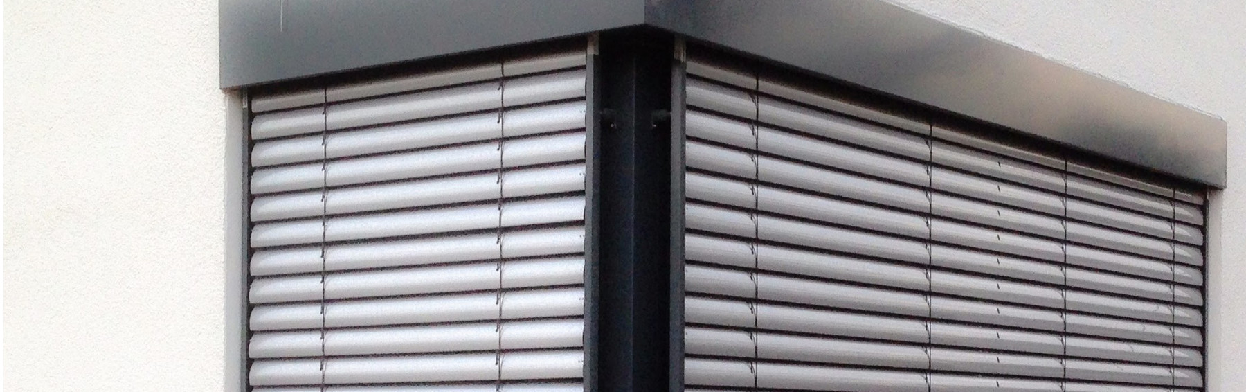
Are all the windows closed when leaving the house? Is the skylight closed when it starts to rain? I asked myself these questions many times after moving into our passive house and looked for a technical solution to automatically detect and evaluate the status of our windows, doors, and locks. The article below deals with the most reliable, convenient, and inexpensive evaluation of these window and door state conditions.
Features
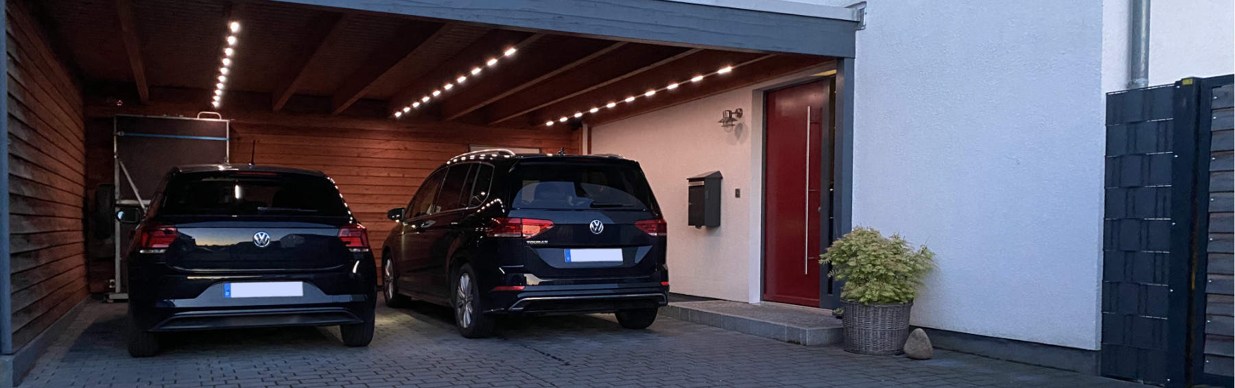
In addition to confirming that all windows and doors are closed when leaving the house (which I have to admit is a bit of an over-engineered feature for our carport), a window and door evaluation also offers many other great features:
For example, we can have the Smart House notify us in summer or winter if a window is left open for too long, either allowing heat to escape unintentionally or to flow into the house.
Also, the unintentional opening of doors and windows can be evaluated as an alarm function.
If we open our front door in the dark, the door sensor automatically switches on the outdoor lighting - much faster than the motion detector installed outside can react.
Finally, the status of all doors and windows can also be used to detect the absence status of the occupants. If neither doors nor windows are opened for a long time, no one is likely at home and the house can automatically switch to absent mode.
Detecting window and door status
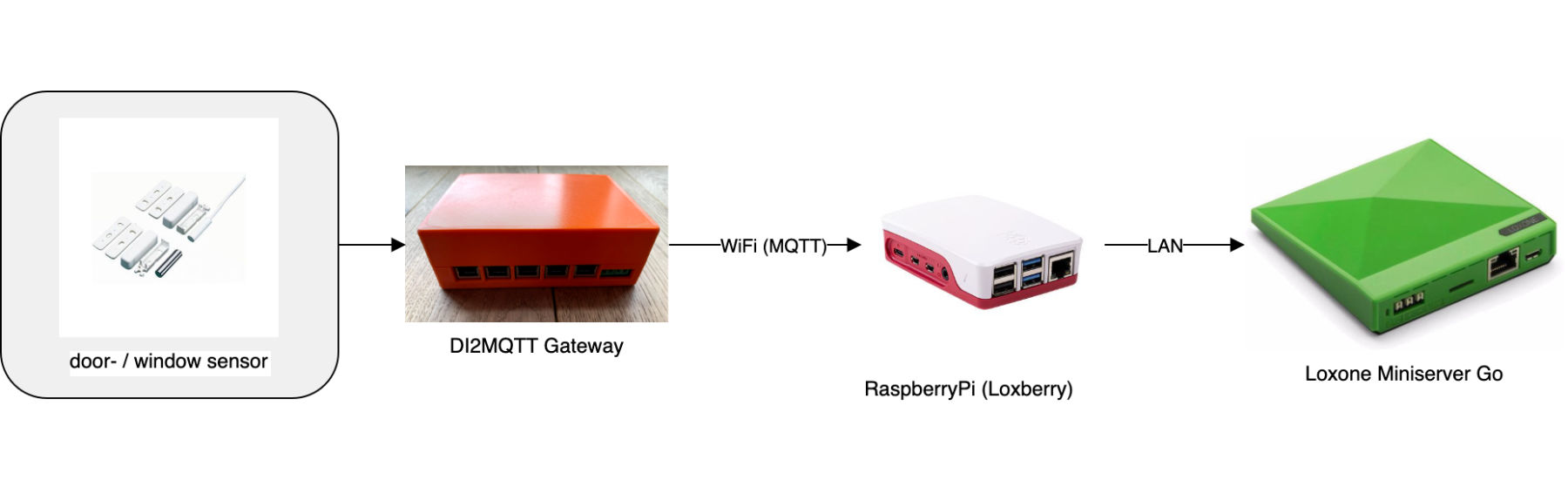
There are numerous ways to track the status of windows and doors in a smart home. When we built our house, we opted for very simple wired reed contacts that transmit their status digitally (1 for closed, 0 for open) to a central location in our laundry room. Whether our doors are locked, indicates a bolt switch contact which is installed in the frame of the door and similarly exits by cable in the utility room.
Commercial products
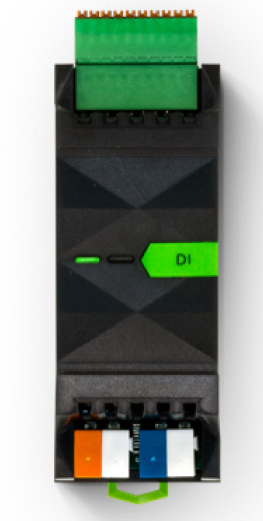
Loxone DI Extension
Including all windows and doors, the digital status of 20 sensors needed to be analyzed for our house. Since I use a Loxone Miniserver Go for managing our smart home, I checked what Loxone offers for this purpose. And indeed, there is the so-called Loxone DI Extension. This offers exactly the 20 digital inputs I need. Unfortunately, this extension costs 250 € (the costs for an additional 24V power supply are not included here).
Since I use various other interfaces besides Loxone in our smart house, I like experimenting and I wanted to develop a smart home device from scratch, I decided to build my own. Price-wise, I am clearly below the solution of Loxone with about 30 € material costs and have all the possibilities to use other brands independent from Loxone with the universal output interface MQTT.
My implementation:
Before going into the technical implementation of my own smart digital interface device, lets take a look at the implemented features first: What does my DI2MQTT interface offer?
- 20 digital inputs
- Status sent via MQTT and thus universally applicable
- Hardware based on ESP32 microcontroller
- Open source SW (hosted on github)
- Connections via screw terminals or Ethernet cable, completely flexible wiring in the housing
Circuit
Concept
The circuit of the DI2MQTT interface is based on using all the digital inputs of an ESP32 microcontroller to be able to evaluate as many window and door sensors as possible. I wanted to be as flexible as possible regarding the assignment of the inputs to the respective wires of the connectors and so I provided a flexible assignment via connector strips. The circuit is completed by LEDs for status indicators (Power, RX, TX) and voltage regulator resp. stabilization.
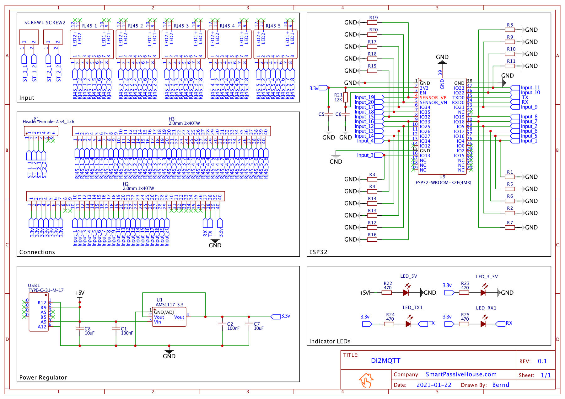
DI2MQTT Circuit diagram
Drawing the circuit
The circuit shown in figure above was created with the free software EasyEDA. The advantage of this software is that you can directly layout the PCB from the circuit. This PCB can be ordered directly from EasyEDA (even with most of the SMD components already assembled).
Components
The following components are required for making the DI2MQTT interface (for a complete list, see the circuit diagram in the “Downloads” chapter):
- ESP32 microcontroller
- USB-C socket
- Various Components for power supply and stabilization
- Connector headers, connection terminal and sockets
- Adapter for first time flashing of the ESP32
PCB layout, ordering and assembly
With EasyEDA I did not only create the schematic, but also the PCB. I decided to use a two-page version. This can be ordered directly out of the EasyEDA software at the company JLCPCB. Since I had planned some SMD components on the board but had no experience with SMD soldering, I decided to use the additional service of JLCPCB to solder the SMD components directly on the board.
The delivery time of the board was a few weeks, but I was more than satisfied with the quality and the result. Especially since I paid less than 24$ for one board including components.
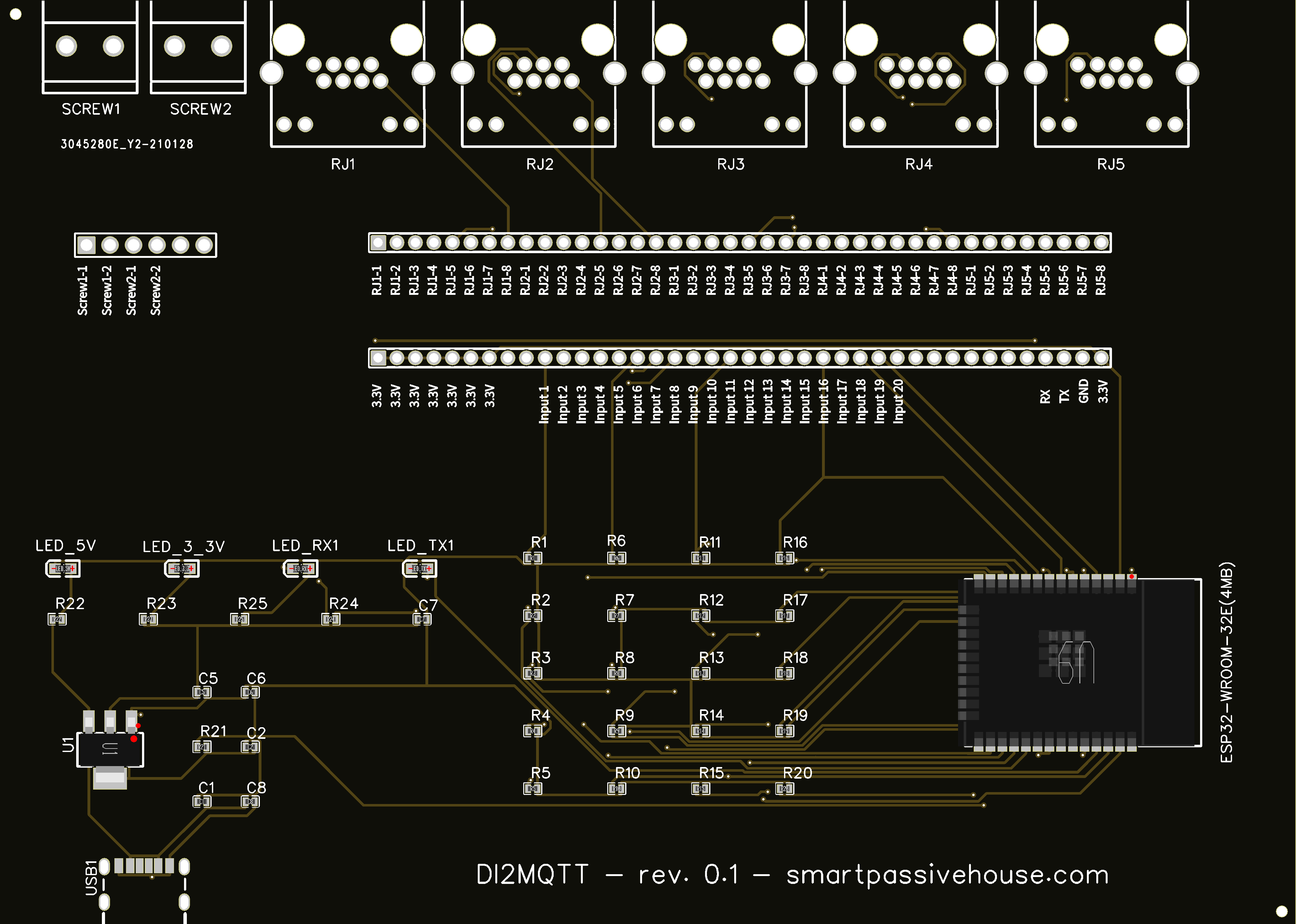
DI2MQTT pcb layout (upside)
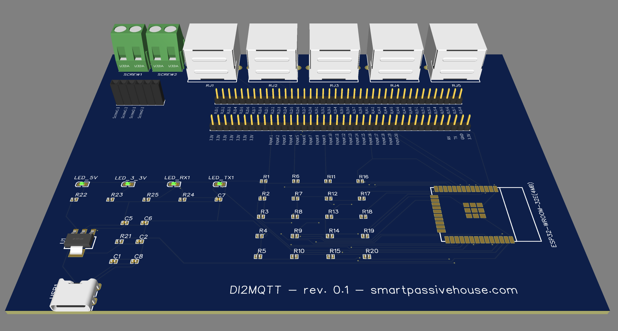
DI2MQTT pcb 3D model

PCB with premounted smd components
Case design
Besides designing my own PCB, I was also new to designing a case. I’ve owned a 3D printer for a while but had no design experience aside from my academic studies. I decided to use Fusion360 and shimmied through a few online tutorials to design a custom enclosure for my own PCB (see the construction files below in the download section). This succeeded on the first try and so the PCB of my DI2MQTT interface now had a suitable housing.
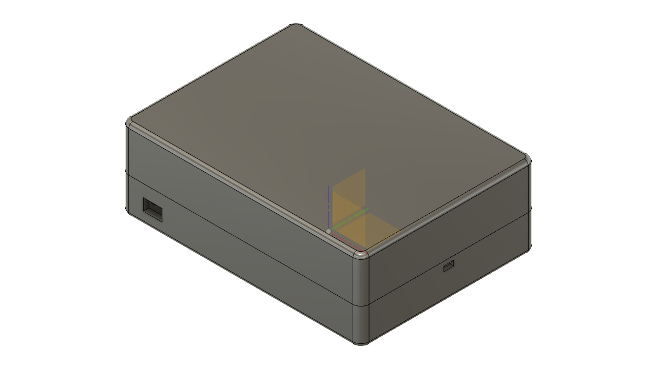
designing case in Fusion 360
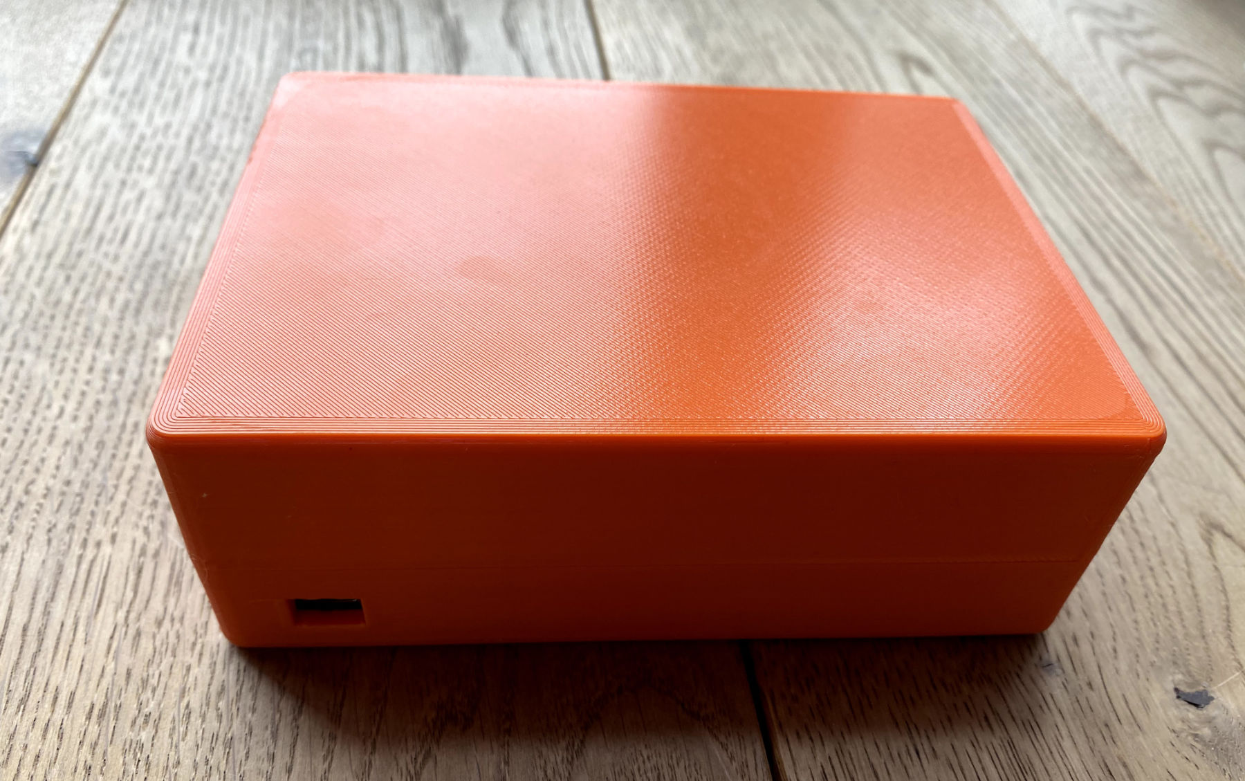
3D Print of DI2MQTT Case (front)
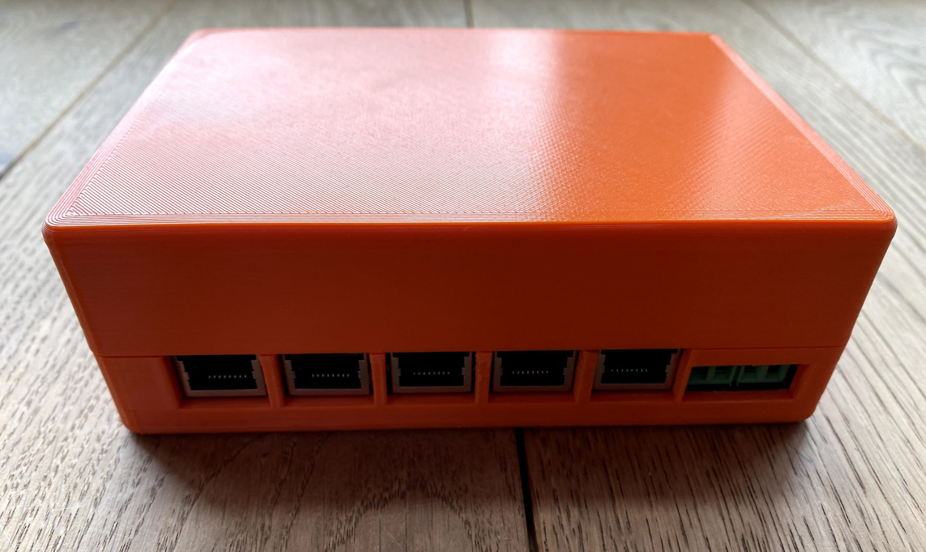
3D Print of DI2MQTT Case (back)
Completed DI2MQTT Interface
After soldering the remaining components that JLCPCB couldn’t assemble directly onto the board and 3D printing the case, all that was left to do was wire up the variable inputs and the board was ready to go. I mounted it next to my Loxone Miniserver Go in our utility room and this completed the hardware part of the DI2MQTT project.
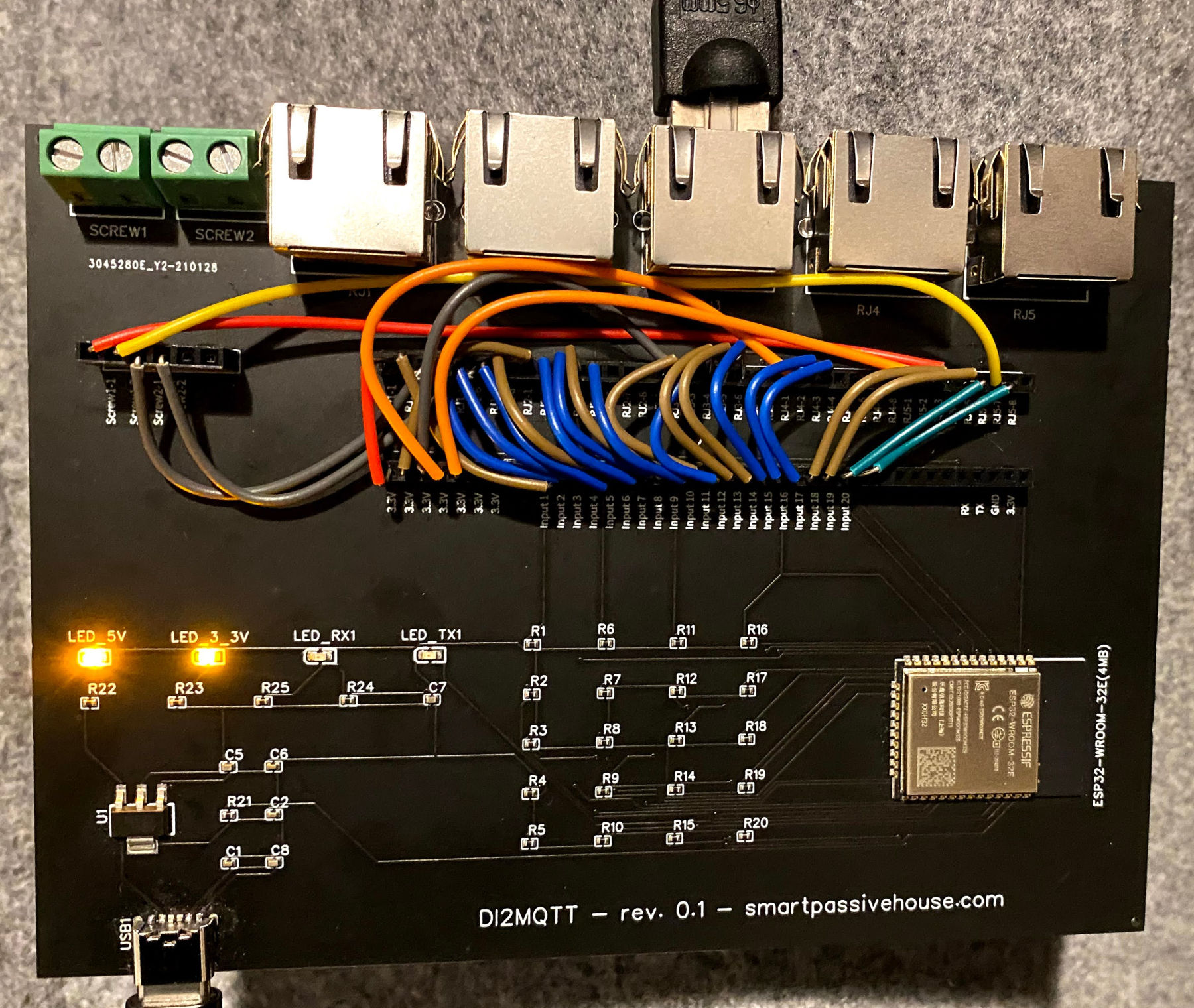
DI2MQTT - all parts mounted
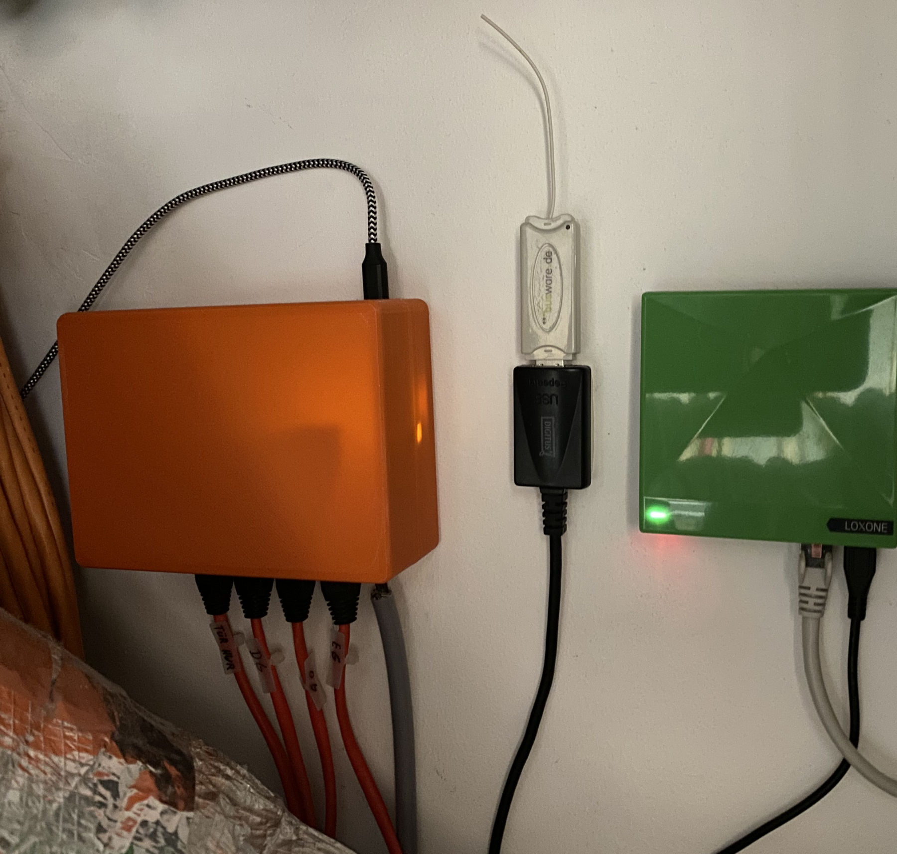
DI2MQTT Hardware ready to operate
Summary & Outlook
In this article, I presented you the hardware part of my first fully electronic project for our Smart House. There were many “first times” for me, as the design of my own PCB or case. In the end, however, many things worked right away, which gave me a lot of confidence for future projects. With the hardware ready to go, it’s time to move on to the software. More about this in part 2.